Thursday, 15 November 2012

lesson 7 making sledge hammer


Making sledge hammer in max
Look at images of hammer for reference 

Create a cylinder and change the sides to 10 in the parametres the reason we do this is because this item isn’t going to be seen up close by the player so it doesn’t need that much detail.Change the height to 3 segments for the same reason. 

Once we have the basic cylinder use the scale tool to scale it in on the X axes to give it a more handle looking shape. (scale tool located in the top tool bar), turn the object into editable poly and select both rings of edges in the centre of the object. (click one edge then click loop or double click another edge)


Scale the edges in on the Y axes until it looks more like a handle, if the model still looks to wide select by element and scale by eye until it looks more realistic. Select the bottom face and right click bevel, change the bevel accordingly to look of the image you used as research.
After you have finished modelling the hammers handle go into the top view and by eye drag out a box over the handle, give this object 3 segments in the length and it is important that the center of the box is align with the center of the hammer.

Select both the box and the handle and then click the align button which is located in the top tool bar (looks like 2 tabs) click both centre in the pop up tab that comes up and click apply followed by click maximum on both by only in the Z axes, click apply and ok.

Go into edge mode on the head of the hammer and ctrl select both edges on ether end, use the ring tool to select a ring of edges around the hammer as shown below.

Right click and select the tick box next to chamfer, change the chamfer until it looks as much like your reference as you can.  After you have chamfered you hammer inset both the end polygons and move them around until there is a slight roundness at each end.

Modifier, unwrap uvw and then go into polygon selection, click the end polygon and click the little plus in the uv tab to grow selection. Once you have the centre polygon and all the surrounding polygons around it go into the projection drop down and click plane, unselect plan and move the selection out of the way, repeat for other side.

Modifier, unwrap uvw and then go into polygon selection, click the end polygon and click the little plus in the uv tab to grow selection. Once you have the centre polygon and all the surrounding polygons around it go into the projection drop down and click plane, unselect plan and move the selection out of the way, repeat for other side.  Do the rest of the hammer in the same way except use the cylinder mapping not the plane. Remember to convert to editable poly after to bake in information.

Do the same for the handle.
Click the handle then go to attach,after clicking attack click the hammer head and then click off attack to make sure your not attaching more things in the scene.


Sunday, 11 November 2012

lesson 6 making tree


Making tree in max


First open the tree image in photoshop make sure it is reasonable symmetrical, then hit CTRL + J to duplicate the background layer and then delete the background of the layer one with the magic wand tool.


Ctrl and left click the thumb nail and creat new layer, fill this layer in white and then create another layer below it and fill this layer is black. Save the image out some where you can find it as a JPEG.


Turn off the top layer off using the eye button and then create a new layer below the layer one, using the petet tool select the darkest color on the tree and then select the bucket tool to fill in this new layer with this dark color.

Select the burn tool on the layer one (mode set to highlights and opacity to 75) start painting over the highlights so they become darker, next create another layer above this layer and turn its layer options to color before going over the edges of the image with the brush tool.


Right click all three layer and merge then, save them out as tree texture.
 
Select the tree by clicking in the white on the top layer with the magic wand tool and then clicking on the background layer,  create new layer and you now have a cut out tree again.
Use the polygonal lasso tool to encircle the top of the tree and create new later to you end up with the same as the image above.
Use ctrl T to select the top of the tree and drag the pivot point down to the bottom so you can rotate it, keep duplicating and rotating until you have gone around 360 degrees.

Make new layer  below this layer after merging all the duplicates together using the merge layer tool (right click) fill this new layer with the dark color from befor.

Create another opacity black and white map the same as you did with the first tree and then save this one with the green background as the texture.
Go into 3ds max and create a plane which is 128 by 93 and then open the material editor, after opening the material editor where it says standard click the button and select multi/ subject and delete the present material so it goes black.


Go into the map selection drop down, load in the diffuse color the texture bitmap and in the opacity selection load in the opacity map for the tree.

Go to the top default layer and drag the texture onto your plane once done go back into the multi/sub object layer and turn show texture on, this will reveal your cut out tree on the plane.
To show your texture on both sides click the 2 sided option at the top of the options above the maps drop down tab.


Hold shift and rotate 45 decrease when the option box comes up select 4 copys to create the same result as the image above. Select all of the planes by pressing ctrl A and convert to editable poly then select one of the planes and click the attach option in the edit poly menu.
After you click attach a box will come up with everything in the scene, select them all and hit attach.


Go to the top view and create a cylinder as wide as the tree.


Convert the cylinder into editable poly and select vertex mode, pulling the vertex’s until the cylinder is cone shaped with a wavy edge.

Apply the textures for the braches onto the cone in the second id  slot the same way we applied them to the original tree plane. After they are applied duplicate and scale until they look similar to the image above.
Add cylinder for trunk.

Sunday, 28 October 2012

lesson 5 high to low poly


Open up the create you made in the previous lesson and go into the uv editor, then break the connections between the different sides and ,move them around so they don’t touch, this will avoid seem errors. (use the pack uv ) this will pack them the most effectively.

Convert to editable poly to bake information.
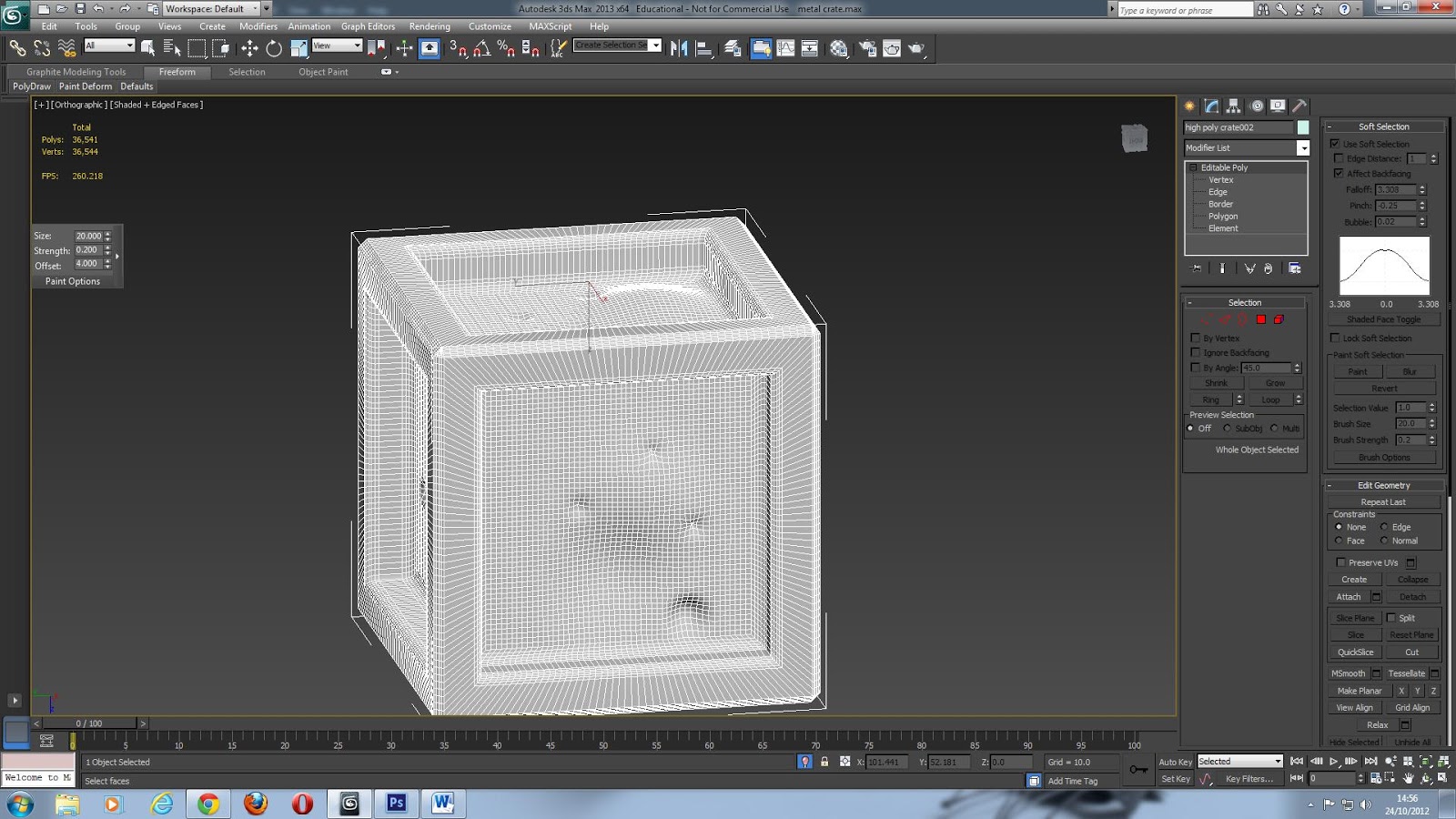
Clone create and rename it high poly create then select the edges by pressing f4


 Click and drag over all of the edges and then deselect all of the corner edges by holding down alt and click on them to make the edges go white.
Click the chamfer button and by eye increase the size of the chamfer and the amount of faces. And use auto smooth at around 20% to round off the edges.
Use the connect tool to increase the level of sub divisions to around 30 000.


 Go into the vertex mode and select soft selections from here you can change the pinch and fall off to make bullet hole shaped dents, you can also make dents by going into freeform selection tab on the left top side of the screen and select the paint deformer.
Unselect the isolate selection and select the low poly and go into modifier list and choose projection.  Once you are in projection go to reference geometry and select high poly crate and click add, go down to the tab that says cage and click shaded to show the detail.
Once you have done this go the tab that’s called cage and increase the amount until the blue lines are higher than the bumps in the high poly.
Go into the rendering drop down and click render to texture select enable projection and then add your low poly create into the output, in the element commons select normal map and increase the size to max. press render if there is red increase the push size.
For the lighting map delete the normal map and change it to a shadows map, go into the render options and under lighting change it from no light to tracer light.


self study 3 making SNES controller in Maya


Wednesday, 17 October 2012

lesson 4 model from reference


  • ·         Created a plane in the front view 48 width by 60 height and then click the shaded option in the wire frame tab (top left of the screen.

·         
  • ·         Press g to get rid of the grid then open the material editor and open the shield image as a defused map, then drag it onto the image.
  • ·         Next we want to freeze the plane so right click the plane and go into object properties, tick the box that says freeze and untick the box that says frozen objects in grey.
  • ·         Create another plane with 4 widths and 6 length right click and go into object properties again and select see through.
  • ·         Turn plane into editable poly and select vertex
  • ·         Using the scale tool scale the verts until they match up with the image starting from the middle.

·         
·         Use the move tool to fix some of the verts that didn’t line up correctly
  • ·         Select by boarder and click on the far outer edge then hold shift and drag back to give the object some depth, make it no see through in the same way you made it see through.

·         
  • ·         Go into the modifier tab and select fD 4 4 4 which gives us a modifier control, go into the editable tab and select the 4 central control points and move them to give some curvature.

·         
  • ·         Convert back into editable poly and then apply a uvw map, flatten mapping in the mapping option.
  • ·         Control I to invert the selection and then click unfold mapping to get the other polygons from the shields boarder.
  • ·         Then as a previous lesson render the image as a map and save it as a jpeg, open in Photoshop
  • ·         Texture the shield and skirting and then save as a Photoshop file.
  • ·         Create a bump map, specular map and color map
  • ·         Use levels to create the spec and bump maps and use the color option in the moderfier list to create the color map
  • ·         Apply the maps the same way you added the diffused map but in there appropriate sections.


·